
The current $I$ through a coil varies with time $t$ as shown in the graph. Plot the graph for the induced $emf$ $e$ versus time $t$ for the coil.
- A
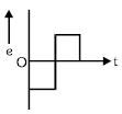
- B
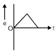
- C
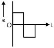
- D
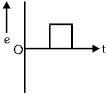
Explore More
Similar Questions
$A$ conducting loop in the shape of a right-angled isosceles triangle of height $10 \ cm$ is kept such that the $90^{\circ}$ vertex is very close to an infinitely long conducting wire (see the figure). The wire is electrically insulated from the loop. The hypotenuse of the triangle is parallel to the wire. The current in the triangular loop is in counterclockwise direction and increases at a constant rate of $10 \ As^{-1}$. Which of the following statement$(s)$ is(are) true?
$(A)$ The magnitude of induced emf in the wire is $\left(\frac{\mu_0}{\pi}\right) \ V$
$(B)$ If the loop is rotated at a constant angular speed about the wire,an additional emf of $\left(\frac{\mu_0}{\pi}\right) \ V$ is induced in the wire
$(C)$ The induced current in the wire is in the opposite direction to the current along the hypotenuse
$(D)$ There is a repulsive force between the wire and the loop
$(A)$ The magnitude of induced emf in the wire is $\left(\frac{\mu_0}{\pi}\right) \ V$
$(B)$ If the loop is rotated at a constant angular speed about the wire,an additional emf of $\left(\frac{\mu_0}{\pi}\right) \ V$ is induced in the wire
$(C)$ The induced current in the wire is in the opposite direction to the current along the hypotenuse
$(D)$ There is a repulsive force between the wire and the loop
$A$ solenoid is oriented end-on so that its opening is perpendicular to the circuit containing the two light bulbs as drawn in figure $C_1.$ For figures $C_2$ and $C_3,$ a shorting wire of negligible resistance is added as shown. Assume that the magnetic field from the solenoid,shown coming out of the plane of the page,decreases uniformly with time at the same rate for each circuit. Rank the circuits for the brightness of the bulb labeled $R_1$ from brightest to dimmest.
Difficult
View Solution$A$ circular insulated copper wire loop is twisted to form two loops of area $A$ and $2A$ as shown in the figure. At the point of crossing,the wires remain electrically insulated from each other. The entire loop lies in the plane of the paper. $A$ uniform magnetic field $\vec{B}$ points into the plane of the paper. At $t=0$,the loop starts rotating about the common diameter as an axis with a constant angular velocity $\omega$ in the magnetic field. Which of the following options is/are correct?
[$A$] The rate of change of the flux is maximum when the plane of the loops is perpendicular to the plane of the paper.
[$B$] The net emf induced due to both the loops is proportional to $\cos \omega t$.
[$C$] The emf induced in the loop is proportional to the sum of the areas of the two loops.
[$D$] The amplitude of the maximum net emf induced due to both the loops is equal to the amplitude of maximum emf induced in the smaller loop alone.
[$A$] The rate of change of the flux is maximum when the plane of the loops is perpendicular to the plane of the paper.
[$B$] The net emf induced due to both the loops is proportional to $\cos \omega t$.
[$C$] The emf induced in the loop is proportional to the sum of the areas of the two loops.
[$D$] The amplitude of the maximum net emf induced due to both the loops is equal to the amplitude of maximum emf induced in the smaller loop alone.
Two inductor coils of self-inductance $3\,H$ and $6\,H$ respectively are connected with a resistance $10\,\Omega$ and a battery $10\,V$ as shown in the figure. The ratio of the total energy stored at steady state in the inductors to that of the heat developed in the resistance in $10\,s$ at the steady state is (neglect mutual inductance between $L_1$ and $L_2$):-
Medium
View SolutionShown in the figure is a circular loop of radius $r$ and resistance $R$. $A$ variable magnetic field of induction $B = B_0 e^{-t}$ is established inside the coil. If the key $K$ is closed,the electrical power developed right after closing the switch is equal to
Difficult
View SolutionVedclass Products
For Students
Vedclass Test Series
Mock tests in real JEE/NEET style with performance analysis. 5-day free trial.
Start Free TrialFor Teachers
Exam Paper Generator
Generate Set A/B/C/D exam papers from 7.5L+ questions in 2 minutes. 3 chapters free.
Try FreeFor Institutes
Online Exam Module
Live online exams with unlimited students, 360° analytics & white-label branding.
See Demo