
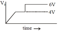
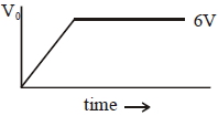
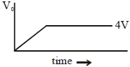
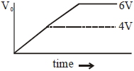
Two Zener diodes ($A$ and $B$) having breakdown voltages of $6\, V$ and $4\, V$ respectively,are connected as shown in the circuit below. The output voltage $V_{0}$ variation with input voltage linearly increasing with time,is given by: $(V_{\text{input}} = 0\, V$ at $t = 0)$ (figures are qualitative).
- A
- B
- C
- D
Explore More
Similar Questions
The $I-V$ characteristics of an electronic device are shown in the figure. The device is $:-$
Easy
View SolutionIn the circuit diagram shown in the figure,the current through the zener diode is (in $mA$)
DifficultMHT CET 2024
View SolutionIn the given circuit, find the voltage drop $V_L$ across the load resistance $R_L$. (in $V$)
What is the current flowing through the Zener diode in the given circuit in $mA$?
Medium
View Solution$A$ Zener diode of power rating $2 \, W$ is to be used as a voltage regulator. If the Zener diode has a breakdown voltage of $10 \, V$ and it has to regulate an unregulated input voltage that fluctuates between $6 \, V$ and $14 \, V$, the value of $R_s$ for safe operation should be $.... \Omega$.
DifficultJEE MAIN 2021
View SolutionVedclass Products
For Students
Vedclass Test Series
Mock tests in real JEE/NEET style with performance analysis. 5-day free trial.
Start Free TrialFor Teachers
Exam Paper Generator
Generate Set A/B/C/D exam papers from 7.5L+ questions in 2 minutes. 3 chapters free.
Try FreeFor Institutes
Online Exam Module
Live online exams with unlimited students, 360° analytics & white-label branding.
See Demo