
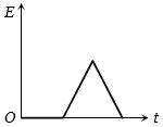
The current $i$ in an induction coil varies with time $t$ according to the graph shown in the figure. Which of the following graphs shows the induced emf $(E)$ in the coil with time?
- A
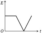
- B
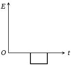
- C
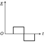
- D
Explore More
Similar Questions
$A$ wire loop is placed in a region of time-varying magnetic field which is oriented orthogonally to the plane of the loop as shown in the figure. The graph shows the magnetic field variation as a function of time. Assume the positive $emf$ is the one which drives a current in the clockwise direction as seen by the observer in the direction of $B$. Which of the following graphs best represents the induced $emf$ as a function of time?
Two metallic rings $A$ and $B$,identical in shape and size but having different resistivities $\rho_A$ and $\rho_B$,are kept on top of two identical solenoids as shown in the figure. When current $I$ is switched on in both the solenoids in an identical manner,the rings $A$ and $B$ jump to heights $h_A$ and $h_B$,respectively,with $h_A > h_B$. The possible relation$(s)$ between their resistivities and their masses $m_A$ and $m_B$ is(are):
$(A)$ $\rho_A > \rho_B$ and $m_A = m_B$
$(B)$ $\rho_A < \rho_B$ and $m_A = m_B$
$(C)$ $\rho_A > \rho_B$ and $m_A > m_B$
$(D)$ $\rho_A < \rho_B$ and $m_A < m_B$
$(A)$ $\rho_A > \rho_B$ and $m_A = m_B$
$(B)$ $\rho_A < \rho_B$ and $m_A = m_B$
$(C)$ $\rho_A > \rho_B$ and $m_A > m_B$
$(D)$ $\rho_A < \rho_B$ and $m_A < m_B$
DifficultIIT 2009
View SolutionTwo similar circular loops carry equal currents in the same direction. On moving the coils further apart,the electric current will
MediumKCET 2008
View SolutionIn the $LR$ circuit shown,what is the variation of the current $I$ as a function of time? The switch is closed at time $t = 0 \, s.$
$A$ source of constant voltage $V$ is connected to a resistance $R$ and two ideal inductors $L_1$ and $L_2$ through a switch $S$ as shown. There is no mutual inductance between the two inductors. The switch $S$ is initially open. At $t=0$,the switch is closed and current begins to flow. Which of the following options is/are correct?
$[A]$ After a long time,the current through $L_1$ will be $\frac{V}{R} \frac{L_2}{L_1+L_2}$
$[B]$ After a long time,the current through $L_2$ will be $\frac{V}{R} \frac{L_1}{L_1+L_2}$
$[C]$ The ratio of the currents through $L_1$ and $L_2$ is fixed at all times $(t>0)$
$[D]$ At $t=0$,the current through the resistance $R$ is $\frac{V}{R}$
$[A]$ After a long time,the current through $L_1$ will be $\frac{V}{R} \frac{L_2}{L_1+L_2}$
$[B]$ After a long time,the current through $L_2$ will be $\frac{V}{R} \frac{L_1}{L_1+L_2}$
$[C]$ The ratio of the currents through $L_1$ and $L_2$ is fixed at all times $(t>0)$
$[D]$ At $t=0$,the current through the resistance $R$ is $\frac{V}{R}$
Vedclass Products
For Students
Vedclass Test Series
Mock tests in real JEE/NEET style with performance analysis. 5-day free trial.
Start Free TrialFor Teachers
Exam Paper Generator
Generate Set A/B/C/D exam papers from 7.5L+ questions in 2 minutes. 3 chapters free.
Try FreeFor Institutes
Online Exam Module
Live online exams with unlimited students, 360° analytics & white-label branding.
See Demo