
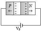
In the case of forward biasing of a $PN-$ junction,which one of the following figures correctly depicts the direction of flow of charge carriers?
- A
- B
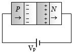
- C
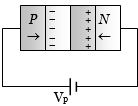
- D
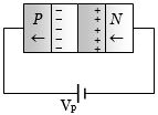
Explore More
Similar Questions
In the circuit shown for the given input voltage $V_i$, the maximum output voltage $V_0$ is
As per the given circuit,the value of current through the battery will be $\dots \; A$.
The reverse biasing in a $PN$ junction diode
The reverse breakdown voltage for a silicon diode is $6 \ V$ for a particular doping concentration and the forward bias voltage drop is $0.3 \ V$. Find the approximate current through the battery in the given circuit in $Amp$.
Medium
View SolutionThe given circuit has two ideal diodes $D_1$ and $D_2$ connected as shown in the figure. The current flowing through the resistance $R_1$ will be (in $\,A$)
Vedclass Products
For Students
Vedclass Test Series
Mock tests in real JEE/NEET style with performance analysis. 5-day free trial.
Start Free TrialFor Teachers
Exam Paper Generator
Generate Set A/B/C/D exam papers from 7.5L+ questions in 2 minutes. 3 chapters free.
Try FreeFor Institutes
Online Exam Module
Live online exams with unlimited students, 360° analytics & white-label branding.
See Demo